 |
Rockhampton
And District Amateur Radio Club |
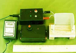
Plugpack battery charger and home brew radio stand |
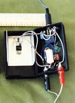
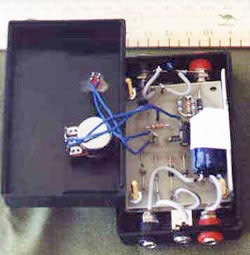
Internal view of the charger
This is a handy little charger that can provide a charging current of up to 120 mA continuously for batteries in the range up to 12 volts.
This project started when I picked up a 12 volt 500 mA plug pack at an
amateur auction at Clareview this year (1999).
Two potentially useful projects resulted from this plug pack. The other
is a variable power supply.
The supply is housed in a small plastic enclosure 90 x 55 x 32 mm.
Circuit Description
Referring to the schematic the incoming
AC supply is rectified with 1 amp bridge, and smoothed with 2 off 100
microfarad capacitors. Current regulation is provided by a 7905
5 volt negative regulator. This regulator is used in computer power
supplies and a few end up in the junk box after a while. By connecting
a resistor between the output and common connection on the 7905 it becomes
a constant current regulator. The current is 5 divided by the resistor
value. Three current settings are available in the circuit as constructed.
The major problem I have with these negative regulator circuits is that
everything has its polarity reversed compared to a positive regulator.
Some care is needed. Two LED's are fitted. One is to indicate that supply
is on to the charger. The other indicates when the unit is charging and
current is flowing. One disadvantage of the 'supply on' LED is that when
the AC supply is switched off the battery will discharge through the LED
circuit.(something that was discovered after the charger was built !)
Leave out the LED.
Construction
The greatest challenge with the power supply is with fitting it into
a small enclosure and to provide sufficient cooling for the series regulator.
The 7905 with two tantalum capacitors is mounted on a piece of 1mm aluminium
60mm x 70mm bent up at two sides to fit into the box. The rest of the
wiring is done using point to point (or ugly) connections. When
everything has been tested and proven the heatsink and LED's are glued
into the enclosure using contact cement. I use Selleys Kwik Grip which
sticks just about everything. The ac input is through a 3.5mm jack plug.
Output uses 4mm banana plugs. Care must be execised to make sure the connections
to the battery are never shorted as the fault current from the battery
is high and will probably blow a fuse in the battery pack or in the radio.
Operation
With no switches on the current is 50mA. This is enough for a slow charge
or sustaining charge on most batteries.
With S1 on a charge of 120mA results. Most hand held batteries will happily
charge at this rate.
With push button S2 on a current of 500mA results. This current may be
useful if one cell in a battery starts to fail and a boost current will
cause the cell to return to normal condition. The advantage with a constant
current charger is if a cell shorts the other cells are not subjected
to a higher current with possible overcharging or over heating.
I have mixed feelings about reviving Ni Cad batteries. Normally the battery
is dead and should be replaced. Only on one pack has the battery seemed
to restore good capacity after a cell shorted and was cleared. Exercise
great care when applying the boost current as if the battery is overheated
it may explode. For this reason use a pushbutton, so that the current
is only applied for a few seconds at a time. When trying to clear a cell
monitor the battery voltage so that when it rises to the correct level
the boost current can be stopped.
 Don
Wilschefski VK4BY June 1999
Don
Wilschefski VK4BY June 1999
This power supply is the result of the use of components at hand (junk box). The core of the project is a number of 2N3055 transistors and a transformer with a 16 volt 18 amp secondary winding.
As it is constructed using the parts I had available at the time it may not be the most cost effective design if all parts are purchased new.
Circuit
Rather than use a more conventional arrangement with a positive supply it was easier to use a negative supply and make use of a 7912 negative regulator as the voltage control. Then by using available NPN transistors to boost output, an output up to 20 amps can be obtained at 12 volts.
Referring to the schematic the incoming AC supply is received in a IEC socket fitted with inbuilt line filters. This will help to keep RF out of the supply. A two pole switch and fuse completes the AC control side to the transformer primary.
The transformer secondary is rectified with a 35 amp full wave rectifier. A 0.01 ohm resistor is in series with the bridge and the filter capacitor to reduce inrush to the capacitor at switch on. (the effect of this resistor is questionable) After the capacitor a 30 amp fuse protects the supply from shorts. The regulator section comprises a 7912 3 terminal regulator with 3 off 2N3055 transistors to boost the output current. The transistors are mounted on a 100x120 heatsink which is fan cooled. The fan is a 12 volt unit controlled by a 60 degree thermostat or a switch on the front panel of the supply. The output then has a number of bypass capacitors to keep RF out of the supply. A LED tells us there is life in the supply.
An over voltage circuit is shown, although it was not constructed in the supply. This uses a specialised over voltage protection IC and an SCR. The SCR shorts the supply after the fuse and blows the fuse if an overvoltage occurs. Overvoltage protection is important because the failure mode of most equipment tends to give a high voltage on the output. There is no point having a $100- power supply destroying $2000- radio equipment.
4.7 microfarad capacitors across the 7912 terminals prevent high frequency
oscillations in this regulator. The 1N4001 diode across the 2N3055's is
there to prevent capacitance in a load destroying the output transistors
when a short occurs in the main filter capacitors or
the overvoltage protection SCR switches on.
Construction
The power supply is housed in a sheet metal box (140H x 150W x 260D mm) that was previously used as a enclosure for a home brew battery charger.
All 240 volt wiring is done in heavy gauge wire with 240 volt rated insulation and sheathed where possible. terminations are enclosed in heatshrink to prevent accidental contact when testing the supply. The fuse is a screw in glass fuse unit on the back panel. The transformer is bolted into the box using heavy brass screws.
The rectifier is mounted on a 3mm aluminum plate approx. 100 x 80 mm. This plate is close to a number of air holes on the enclosure where ventilation air enters. The thermostat is also mounted on this heat sink.
The filter capacitor is bolted to the floor of the enclosure. The regulator is mounted on the capacitor terminals on a small veroboard circuit board. It has a small heatsink.
The most complicated part of the construction is the mounting of the fan and ensuring the cooling air is directed across the heatsinks. The three output transistors are mounted on a heatsink on the back of the supply. Under the heatsink a number of holes are drilled in the back of the supply to allow air to pass out of the supply to the heat sink. Inside the supply the the fan is mounted just inside the supply on brackets to seal the fan against the back wall of the supply. Air is drawn into the supply enclosure through holes adjacent to the rectifier heatsink. In the way described both heatsinks receive a supply of cooling air.
Output terminals are four off 4mm banana sockets for plus and minus connections. The bypass capacitors are mounted directly across the output terminals to stop any entry of RF.
Operation
Testing involved applying loads to the output and checking the temperature
rise was not excessive. More sophisticated tests can be conducted if necessary
to determine output voltage stability as loads change.
Disclaimer
This circuit uses mains circuitry operating at mains voltages.
It is not a detailed description with full constructional details etc.
Constructors should confirm all design calculations before using this
design. The power supply should not be used in un-manned situations.
In those situations more sophisticated protection is required to prevent
fire if a fault occurs.
Don Wilschefski VK4BY June 1999
This is a handy little power supply that can provide a voltage range of 1.25 to 13 volts and current up to 500 mA.
This project started when I picked up a 12 volt 500 mA plug pack at an
amateur auction at Clareview this year (1999).
Two potentially useful projects resulted from this plug pack. The other
is a Ni Cad battery charger.
The supply is housed in a small plastic enclosure 90 x 55 x 32 mm.
Circuit
Referring to the schematic the incoming AC supply is rectified with four 1 amp 100 volt diodes, and smoothed with 1000 microfarad capacitor. Then a conventional LM317 circuit variable power supply follows. The value of R1 was fiddled to get the correct maximum voltage for the circuit to give 13 volts. The sockets that are connected to the bridge rectifier allow AC input via 3.5mm jack plug or a DC input via banana plugs. This allows the regulator to be used with a DC fixed supply if a smaller voltage is required. (for example as a 6 volt supply for a child's noise box in the car when the dry cell battery budget expires!) The output terminals are also 4mm banana plugs. connecting the input voltage incorrectly should destry the LM317 so some care is required, or use a polarised plug for this input.
The circuit board is based on DSE kit K3592 described in Silicon Chip
in May 1992.
Construction
The greatest challenge with the power supply is with fitting it into
a small enclosure and to provide sufficient cooling for the series regulator.
The LM317 is mounted on a piece of 1mm aluminium 60mm x 70mm bent up at
one side to fit into the box. The PCB for the circuit is screwed to the
aluminum with four screws and spacers. When everything has been tested
and proven the heatsink is glued into the enclosure using contact cement.
I use Selleys Kwik Grip which sticks just about everything.
Operation
With the components as shown the supply can supply from 1.25 to 13 volts. The major limitation is with the plug pack. The voltage drops as load is applied so at 12 volts it is not capable of much more than 300mA before the voltage starts to drop. the little plug packs do not have good regulation. Below 9 volts the supply is good for 500 mA. Watch the heat generated when operating at lower voltages and load above 100 mA as the power dissipated by the heat sink increases.
A plug pack with a higher current or voltage rating will give a better output at 12 volts. Similarly a bigger heatsink will give less temperature rise in the unit when low voltages and high currents are used.
Don Wilschefski VK4BY June 1999